Personvernerklæring: Ditt personvern er veldig viktig for oss. Vårt selskap lover å ikke røpe din personlige informasjon til noen ekspanien til de eksplisitte tillatelsene dine.
Modell nr.: NSO4GU3AB
Transport: Ocean,Air,Express,Land
Betalings type: L/C,T/T,D/A
Incoterm: FOB,EXW,CIF
4 GB 1600MHz 240-pinners DDR3 udimm
Endringshistorikk
|
Revision No. |
History |
Draft Date |
Remark |
|
1.0 |
Initial Release |
Apr. 2022 |
|
![]()
Bestilling av informasjonstabell
|
Model |
Density |
Speed |
Organization |
Component Composition |
|
NS04GU3AB |
4GB |
1600MHz |
512Mx64bit |
DDR3 256Mx8 *16 |
Beskrivelse
Hengstar ubufret DDR3 SDRAM DIMMS (ubuffered dobbel datahastighet synkrone dram dobbelt in-line minnemoduler) er lav effekt, høyhastighets driftsminnemoduler som bruker DDR3 SDRAM-enheter. NS04GU3AB er en 512m x 64-bits to rangering 4GB DDR3-1600 CL11 1,5V SDRAM Unbuffered DIMM-produkt, basert på seksten 256m x 8-bit FBGA-komponenter. SPD er programmert til JEDEC Standard Latency DDR3-1600-tidspunktet 11-11-11 ved 1,5V. Hver 240-pinners DIMM bruker gullkontaktfingre. SDRAM ubufferet DIMM er beregnet på bruk som hovedminne når den er installert i systemer som PCer og arbeidsstasjoner.
Egenskaper
Kraftforsyning: VDD = 1,5V (1.425V til 1.575V)
VDDQ = 1,5V (1.425V til 1.575V)
800MHz FCK for 1600MB/SEC/PIN
8 uavhengig intern bank
Programmerbar CAS -latens: 11, 10, 9, 8, 7, 6
Programmerbar additiv latens: 0, CL - 2 eller CL - 1 klokke
8-biters forhåndsfremstilling
Burst Lengde: 8 (Innblanding uten grense, sekvensiell med startadresse “000”), 4 med TCCD = 4 som ikke tillater sømløs lesing eller skriv [enten på farten ved hjelp av A12 eller MRS]
Bi-retningsdelingsdifferensialdata Strobe
Intern (selv) kalibrering; Intern selvkalibrering gjennom ZQ PIN (RZQ: 240 Ohm ± 1%)
Die terminering ved hjelp av ODT -pin
Overgrepsoppdateringsperiode 7.8Us ved lavere enn Tcase 85 ° C, 3,9Us ved 85 ° C <Tcase <95 ° C
Synkron tilbakestilling
Tilpassbar data-output Drive Styrke
Fly-by topology
PCB: Høyde 1.18 ”(30mm)
ROHS-kompatibel og halogenfri
Key Timing -parametere
|
MT/s |
tRCD(ns) |
tRP(ns) |
tRC(ns) |
CL-tRCD-tRP |
|
DDR3-1600 |
13.125 |
13.125 |
48.125 |
2011/11/11 |
Adressebord
|
Configuration |
Refresh count |
Row address |
Device bank address |
Device configuration |
Column Address |
Module rank address |
|
4GB |
8K |
32K A[14:0] |
8 BA[2:0] |
2Gb (256 Meg x 8) |
1K A[9:0] |
2 S#[1:0] |
PIN -beskrivelser
|
Symbol |
Type |
Description |
|
Ax |
Input |
Address inputs: Provide the row address for ACTIVE commands, and the column |
|
BAx |
Input |
Bank address inputs: Define the device bank to which an ACTIVE, READ, WRITE, or |
|
CKx, |
Input |
Clock: Differential clock inputs. All control, command, and address input signals are |
|
CKEx |
Input |
Clock enable: Enables (registered HIGH) and disables (registered LOW) internal circuitry |
|
DMx |
Input |
Data mask (x8 devices only): DM is an input mask signal for write data. Input data is |
|
ODTx |
Input |
On-die termination: Enables (registered HIGH) and disables (registered LOW) |
|
Par_In |
Input |
Parity input: Parity bit for Ax, RAS#, CAS#, and WE#. |
|
RAS#, |
Input |
Command inputs: RAS#, CAS#, and WE# (along with S#) define the command being |
|
RESET# |
Input |
Reset: RESET# is an active LOW asychronous input that is connected to each DRAM and |
|
Sx# |
Input |
Chip select: Enables (registered LOW) and disables (registered HIGH) the command |
|
SAx |
Input |
Serial address inputs: Used to configure the temperature sensor/SPD EEPROM address |
|
SCL |
Input |
Serial |
|
CBx |
I/O |
Check bits: Used for system error detection and correction. |
|
DQx |
I/O |
Data input/output: Bidirectional data bus. |
|
DQSx, |
I/O |
Data strobe: Differential data strobes. Output with read data; edge-aligned with read data; |
|
SDA |
I/O |
Serial |
|
TDQSx, |
Output |
Redundant data strobe (x8 devices only): TDQS is enabled/disabled via the LOAD |
|
Err_Out# |
Output (open |
Parity error output: Parity error found on the command and address bus. |
|
EVENT# |
Output (open |
Temperature event: The EVENT# pin is asserted by the temperature sensor when critical |
|
VDD |
Supply |
Power supply: 1.35V (1.283–1.45V) backward-compatible to 1.5V (1.425–1.575V). The |
|
VDDSPD |
Supply |
Temperature sensor/SPD EEPROM power supply: 3.0–3.6V. |
|
VREFCA |
Supply |
Reference voltage: Control, command, and address VDD/2. |
|
VREFDQ |
Supply |
Reference voltage: DQ, DM VDD/2. |
|
VSS |
Supply |
Ground. |
|
VTT |
Supply |
Termination voltage: Used for control, command, and address VDD/2. |
|
NC |
– |
No connect: These pins are not connected on the module. |
|
NF |
– |
No function: These pins are connected within the module, but provide no functionality. |
Merknader : Tabellen PIN -beskrivelsen nedenfor er en omfattende liste over alle mulige pinner for alle DDR3 -moduler. Alle listede pinner kan ikke støttes på denne modulen. Se PIN -er for informasjon som er spesifikk for denne modulen.
Funksjonell blokkdiagram
4 GB, 512mx64 modul (2rank av x8)


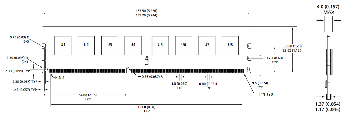
Moduldimensjoner
Forfra

Forfra

Merknader:
1. Alle dimensjoner er i millimeter (tommer); Maks/min eller typisk (typ) der det er nevnt.
2. Toleranse på alle dimensjoner ± 0,15 mm med mindre annet er spesifisert.
3. Dimensjonsdiagrammet er kun for referanse.
Produkt kategorier : Industrial Smart Module Accessories


Personvernerklæring: Ditt personvern er veldig viktig for oss. Vårt selskap lover å ikke røpe din personlige informasjon til noen ekspanien til de eksplisitte tillatelsene dine.

Fyll ut mer informasjon slik at det kan komme i kontakt med deg raskere
Personvernerklæring: Ditt personvern er veldig viktig for oss. Vårt selskap lover å ikke røpe din personlige informasjon til noen ekspanien til de eksplisitte tillatelsene dine.